Fantastic Combination Motor Starter Wiring Diagram

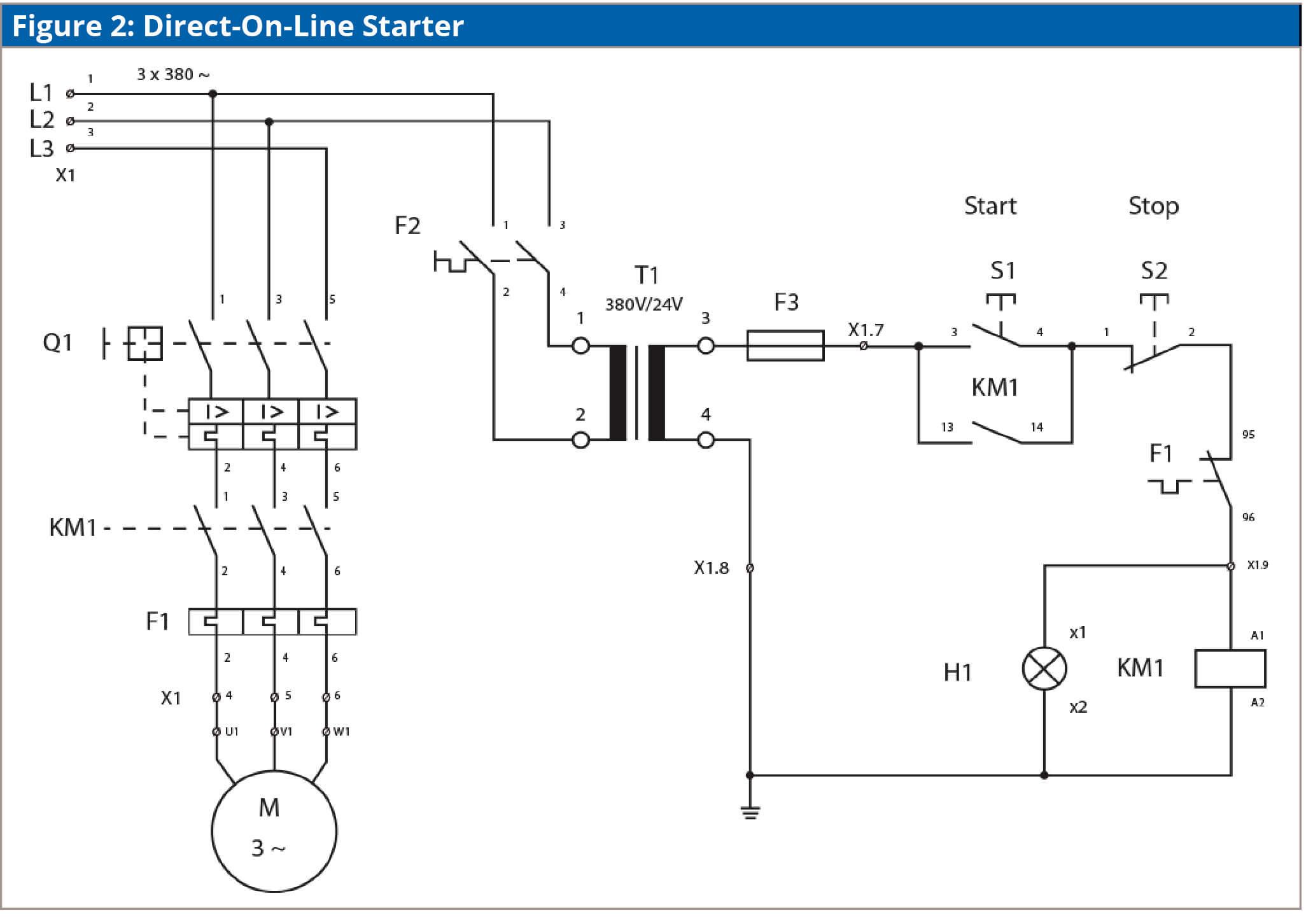
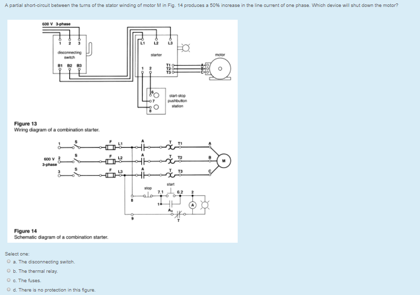
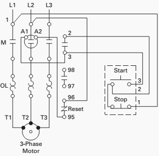
Line diagrams show circuits of the operation of the controller.
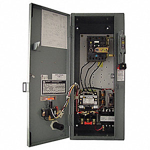
Combination motor starter wiring diagram. Improper wiring can kill injure start fires burn out motors or any all of the above. Class 8538 combination starters can be furnished with either a fusible or non fusible disconnect switch. In north america an induction motor will typically operate at 230v or 460v 3 phase 60 hz and has a control voltage of 115 vac or 24 vdc.
When the forward contacts f close l1 l2 and l3 are con nected to t1 t2 and t3 just as they would be on a non reversing starter. A motor starter is a combination of devices used to start run and stop an ac induction motor based on commands from an operator or a controller. Please refer to the manufacturer s literature if in doubt.
Several other combinations are possible in north america and other countries and are easily derived from the. Interchangeable fuse clips straight through wiring space for a. Your motor starter may use wiring which is internal to the starter wiring which is different than the diagrams etc.
Shows the wiring diagram for a full voltage mag netic reversing starter. Line diagrams also called schematic or elementary diagrams show the circuits which form the basic operation of the controller. When the reverse contacts r close the motor is connected l1 to t3 l2 to t2 and l3 to t1.
3ph starter 3ph motor line voltage. Figure 1 is a typical wiring diagram for a three phase magnetic motor starter. Class 8538 combination starters are available in nema size 0 6.
If you are not sure of how to make the connections on your equipment hire an electrician.


