Great Start Stop Using One Button Ladder Diagram

Simulate this circuit schematic created using circuitlab.
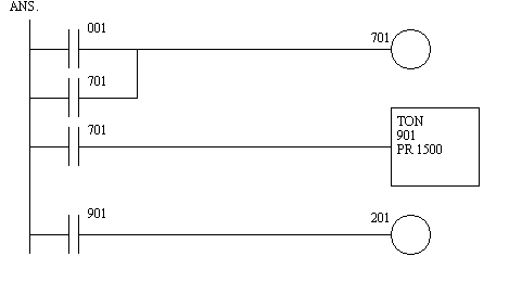
Start stop using one button ladder diagram. Learn how to use single push button to on and off a bulb using ladder logic in programmable logic controllers plc control system. So when the start button is pushed the plc input changes state from false to true. Ask question asked 2 years 11.
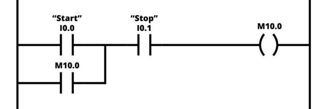
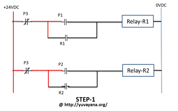
Simple ladder logic for motor control using push button start stop logic includes a start button stop button motor thermal overload and motor run contactor. Bac6d916 a9ab 467b 8621 fe5a4176d5fc jpeg 150 downloads last edited by. Start button or plc input i0 0.
It means that same button will be use as off and on function. Here in the above logic once motor started with test push button we have to use stop push button for stopping the motor. Can anybody do this for me.
This is how the ladder diagram looks for a simple start stop function. As soon as the push button i0 0 n o is pressed it becomes n c and coil q1 5 flag is energized the another flag q1 6 will not energize as. Share improve this.
Input push button normally open q0 0. The start button will activate the relay or ladder logic relay m10 0. Stop button or plc input i0 1.
In this ladder logic example there are two inputs. In this case the logic looks. Pressing on engages the relay.
