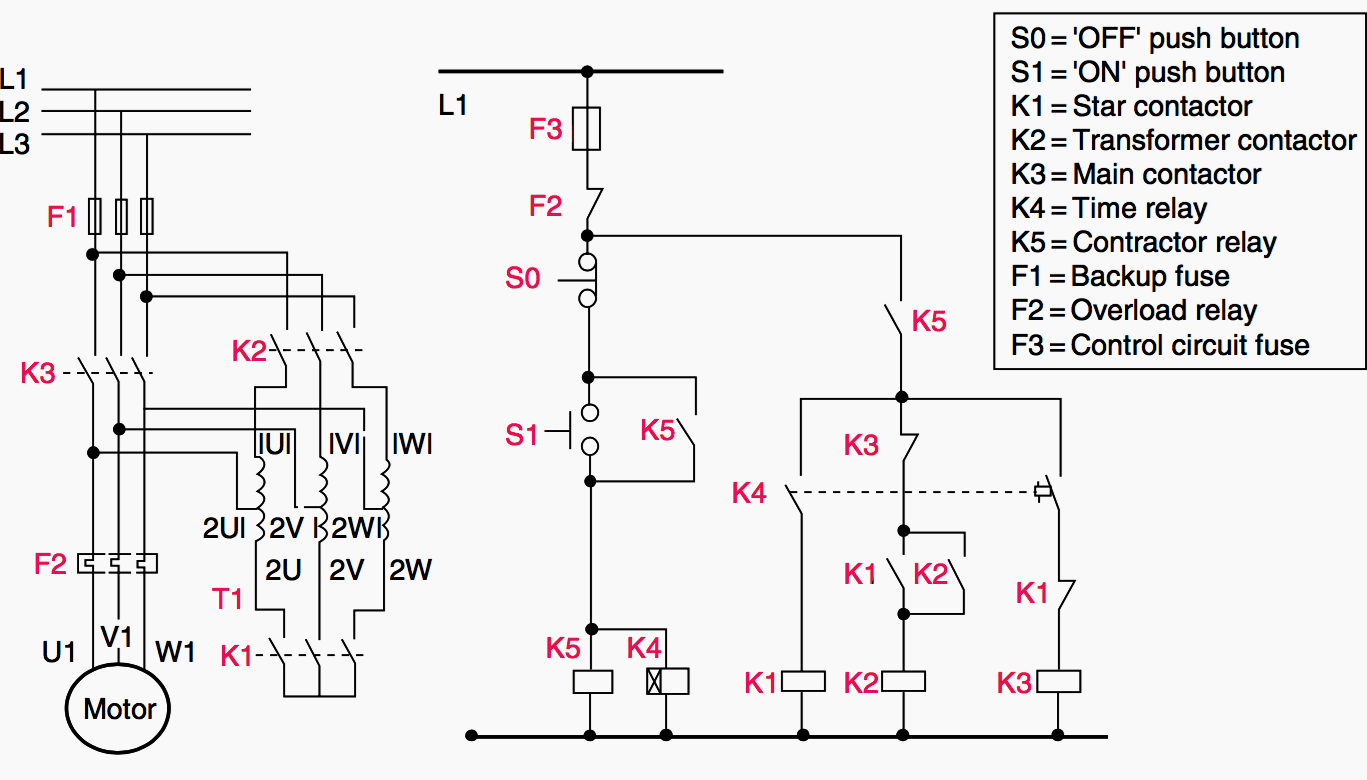
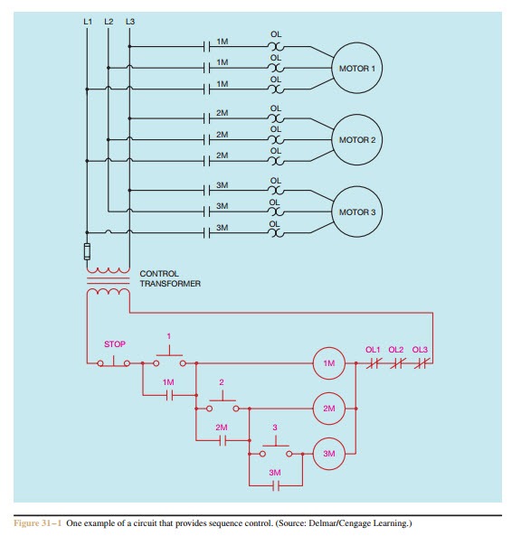
Fine Beautiful Sequential Control Of Three Motors Diagram

Sequence Control For Industrial Motors

Sequence Control For Industrial Motors 220 Circuit Breaker 4 Pin Toggle Switch Wiring

Sequence Control Sequence Control Circuit 1 And Sequence Control Circuit 2 Electric Equipment

Sequence Control Circuit 1 And 2 Electric Equipment 6 Wire Washing Machine Motor Wiring Diagram Dryer 3 Prong To 4 Adapter

Sequence Control Basic Control Circuits
Sequence Control Basic Circuits Dual Source Energy Meter Wiring Diagram Four Prong Trailer Plug
Sequence Controls For Motor Starters
Sequence Controls For Motor Starters Slip Ring Rotor Diagram Types Of Dc With
Troubleshooting Three Basic Hardwired Control Circuits Used In Starting Electric Motor Eep

Troubleshooting Three Basic Hardwired Control Circuits Used In Starting Electric Motor Eep 220 Breaker Box Wiring Diagram Gooseneck Trailer

5 Contactor Circuits
5 Contactor Circuits Trailer Light Wiring Diagram 6 Wire Bathroom Fan Switch
5 Contactor Circuits

With this knowledge ladder logic diagrams can be converted to sequential function charts ad vice versa.

Sequential control of three motors diagram. Enjoy the videos and music you love upload original content and share it all with friends family and the world on youtube. One motor cannot start until some other motor is in operation. So that whole operation will take 10 seconds to start all motors in a sequence.

The program is used to carry out the sequential switching on our 3 motors a b and c when the start switch is closed motor a starts 10 seconds later motor b start and after 30 sec motor c start draw the ladder diagram of control. Sequence control is used by such machines as hydraulic presses that must have a high pressure pump operating before it can be used or by some air conditioning systems that require that the blower be in operation before the compressor starts. 19 less than a minute.

There are total 3 motors to be controlled in a sequence. A simple circuit diagram of contactor with three phase motor. Control motors protection a simple circuit diagram of contactor with three phase motor.

If either out 2 or out 3 is realized along with the transition condition in 4 step 4 is activated. So that each motor will start sequentially say motor 1 will start then after some delay then motor 2 will start and after some delay motor 3 will start. Sequence control forces motors to start or stop in a pre determined order.

Three phase electrical wiring installation in home iec nec. 19 less than a minute. Facebook twitter linkedin tumblr pinterest reddit vkontakte skype messenger messenger whatsapp telegram share via email print.

One example of electrical control applied to ma. This is an overview of the basic structure of sfcs. Multi speed 3 phase motor 3 speeds 1 direction power control diagrams one line diagram of simple contactor circuit.

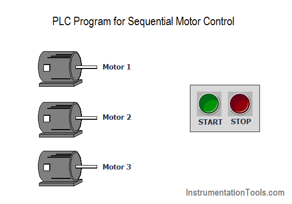
Plc Program For Sequential Motor Control Plc Motor Programming

Plc Program For Sequential Motor Control Programming 7 Pin To 4 Trailer Adapter Autozone Three Phase Winding Diagram

How A 3 Phase Motor Control Circuit Works Youtube
How A 3 Phase Motor Control Circuit Works Youtube 2 Black And 1 Red Wire 7 Pin Trailer Connections
Ac Motor Control Circuits Worksheet Ac Electric Circuits
Ac Motor Control Circuits Worksheet Electric Motion Sensor Switch No Neutral Ground Doorbell Chime Diagram
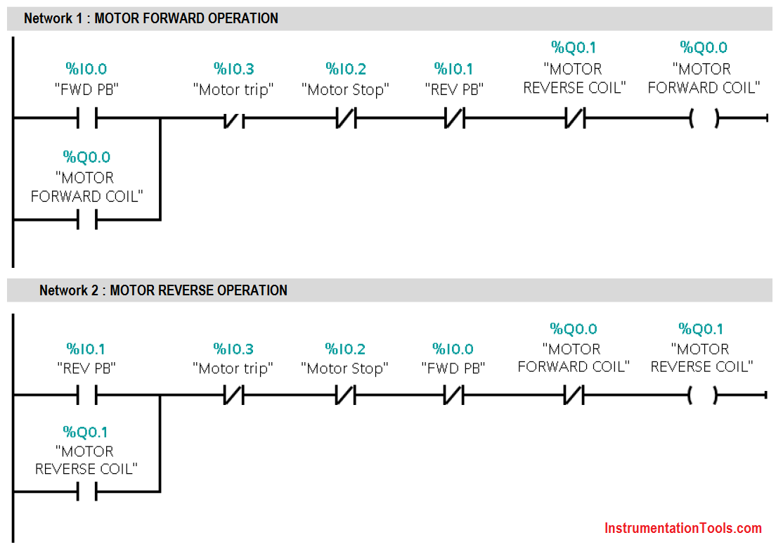
3 Phase Motor Control Using Plc Ladder Logic Plc Tutorials Point

3 Phase Motor Control Using Plc Ladder Logic Tutorials Point Mcc Panel Wiring Royu Outlet Diagram

Forward Reverse Control

Forward Reverse Control Motorcycle Horn Wiring Diagram 2004 Nissan 350z Radio

Phase Controller Wiring Phase Failure Relay Diagram Electrical Wiring Basic Electrical Wiring Electrical Wiring Diagram
Phase Controller Wiring Failure Relay Diagram Electrical Basic 12v Toggle Switch Home Layout
Plc Program Three Phase Motor Plc Programming Ladder Logic Programming

Plc Program Three Phase Motor Programming Ladder Logic Towsmart Wiring Diagram 2007 Nissan Titan Fuse Box

Plc Application For Reduced Voltage Start Motor Control Eep Electrical Circuit Diagram Ladder Logic Circuit Diagram

Plc Application For Reduced Voltage Start Motor Control Eep Electrical Circuit Diagram Ladder Logic 6 Pole Toggle Switch Wiring Water Pump Float

Dol Starter Panel Wiring Diagram Save Start Stop And Motor Electrical Circuit Diagram Circuit Diagram Electric Circuit

Dol Starter Panel Wiring Diagram Save Start Stop And Motor Electrical Circuit Electric Dometic Rv Thermostat Two Switch Light