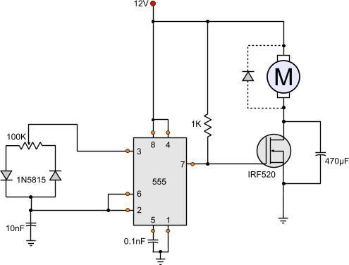
Outrageous Dc Motor Schematic Diagram

12 Volt Dc Motor Speed Controller Circuit Diagram Motor Speed Circuit

12 Volt Dc Motor Speed Controller Circuit Diagram Momentary Toggle Switch Wiring 3 Phase Isolator

Dc Motor Control Circuit Diagram Electrical Engineering Blog Circuit Diagram Electrical Circuit Diagram Electronic Circuit Design

Dc Motor Control Circuit Diagram Electrical Engineering Blog Electronic Design 2005 Chevy Trailblazer Radio Wiring Harness Outlet And Switch In Same Box

Dc Motor Braking Circuit Diagram Elec Eng World Circuit Diagram Electrical Motors Circuit

Dc Motor Braking Circuit Diagram Elec Eng World Electrical Motors Ceiling Fan Switch 3 Speed 4 Wire Trailer Connector

How To Build A Simple Pwm Dc Motor Speed Controller Using Atmega8 Microcontroller Mosfet And Pot Youtube Motor Speed Microcontrollers Circuit Diagram
How To Build A Simple Pwm Dc Motor Speed Controller Using Atmega8 Microcontroller Mosfet And Pot Youtube Microcontrollers Circuit Diagram 2 Wire Gfci Outlet 15 Pin Trailer Connector
Schematic Diagram Of Speed Controlled D C Motor Drive Eee
Schematic Diagram Of Speed Controlled D C Motor Drive Eee Gfci Plug Wiring 2001 Honda Civic Stereo Harness
Bodine Electric Motor Wiring In 2020 Electric Motor General Electric Capacitors

Bodine Electric Motor Wiring In 2020 General Capacitors 4 Light Switch Changing 3 Prong To Dryer

Bodine Electric Motor Wiring In 2020 Electric Motor General Electric Capacitors

Connect the motor external positive and negative supply to the terminal block e and e.

Dc motor schematic diagram. In case of the shunt wound dc motor this current supply will divide into two ways like ia ish where ia will supply throughout the ra resistance armature winding. The timer chip which applied in this circuit will be an nmos dual timer oscillator ne556. This timer ic has two 555 timers in a single 14 pin ic package.

When voltage is applied current flows from power supply terminals through the series winding and armature winding. We know that ish e rsh. In the electrical sector a schematic diagram is usually used to describe the design or model of equipment.

Dc series motor circuit diagram in a series motor electric power is supplied between one end of the series field windings and one end of the armature. The above diagram shows how to connect the l298 ic to control two motors. Figure 6 shows the counter emf starter circuit diagram.

Dc motor speed controller. Following is the schematic diagram of the dc motor interface to arduino uno board. This schematic diagram come from circuit.

Definite time dc motor starter circuit diagram. In the same way ish will supply through the rsh resistance field winding. The coils pi and p2 are selected to have pickup voltages at the desired values of counter emf.

The circuit applies two oscillators timers which are connected as a pulse width modulator pwm. One way to ensure the armature current is held to a reasonable level is to measure the counter emf and remove starting resistors at predetermined values of emf. There are three input pins for each motor input1 in1 input2 in2 and enable1 en1 for motor1 and input3 input4 and enable2 for motor2.

Pin On Electronics Circuit

Pin On Electronics Circuit 2 Gang Wiring Float Switch To Bilge Pump

Dc Motors And Stepper Motors Used As Actuators Electronic Engineering Electronic Schematics Electronics Circuit

Dc Motors And Stepper Used As Actuators Electronic Engineering Schematics Electronics Circuit Telecaster Wiring Diagram 3 Way Switch Humbucker Single Pole To

555 Dc Motor Speed Control Circuit Diagram Motor Speed Circuit

555 Dc Motor Speed Control Circuit Diagram Somfy Wiring Boss Bv9976b Harness

Free Electronics Circuits에 있는 핀

Dc Train Motors Electrical Wiring Diagram Electrical Wiring Electrical Diagram

Dc Train Motors Electrical Wiring Diagram Euro Trailer Plug Rv Ac

Arduino Dc Motor Control Using L298n Motor Driver Pwm H Bridge Electronics Mini Projects Arduino Electronic Circuit Projects

Arduino Dc Motor Control Using L298n Driver Pwm H Bridge Electronics Mini Projects Electronic Circuit Wiring Switch Box 2 Light Diagram

Pin On Circuit

Pin On Circuit Two Way Switch Wiring Diagram Lights Asco Transfer

Pin On Electronics

Pin On Electronics Small Trailer Wiring Diagram Ethernet Cable

Pin On Gadgets And Circuits
Pin On Gadgets And Circuits Chrysler Infinity Amp Wiring Diagram Car Cfl Lamp Circuit